Ask Latest Price
Active Member
5 Years

CHIFON ELECTRIC CO.,LIMITED
BEST SERVICE, WE DRIVE!


Add to Cart
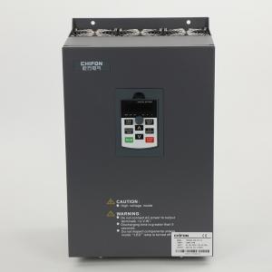
132kw Forced Convection Variable Speed Drive VFD 380V 3 Phase For Foaming Machine

What is a Variable Speed Drive?
A variable frequency drive (VFD) is an electronic device that controls the speed of AC induction motors. Before we look at how this works and how it can be used, we should look at the history of motor controllers, and also how the induction motor itself works.
It has always been useful to control the speed of electric motors used in industry. Nearly every process that uses a motor will benefit from speed control. Not only is the process generally improved, but in many cases (particularly with pumps and fans) these are considerable energy savings.
Before electronic controllers were available, motors were controlled in various ways, for example by controlling the field current on a DC motor using a series of resistors, or by using other motors. However, when Thyristors, the first power semiconductors, became available in the 1950s, it became possible to control the armature voltage, and therefore the speed, of a DC motor using phase control. These DC drives are still manufactured and in wide use today.
Why do we need a VFD?
If you have an application that does not need to be run at full speed, then you can cut down energy costs by controlling the motor with a variable frequency drive, which is one of the benefits of Variable Frequency Drives. VFDs allow you to match the speed of the motor-driven equipment to the load requirement. There is no other method of AC electric motor control that allows you to accomplish this.
Electric motor systems are responsible for more than 65% of the power consumption in the industry today. Optimizing motor control systems by installing or upgrading to VFDs can reduce energy consumption in your facility by as much as 70%. Additionally, the utilization of VFDs improves product quality and reduces production costs. Combining energy efficiency tax incentives, and utility rebates, returns on investment for VFD installations can be as little as 6 months.
By operating your motors at the most efficient speed for your application, fewer mistakes will occur, and thus, production levels will increase, which earns your company higher revenues. On conveyors and belts, you eliminate jerks on start-up allowing high throughput.
Your equipment will last longer and will have less downtime due to maintenance when it’s controlled by VFDs ensuring optimal motor application speed. Because of the VFDs optimal control of the motor’s frequency and voltage, the VFD will offer better protection for your motor from issues such as electrothermal overloads, phase protection, under-voltage, overvoltage, etc.. When you start a load with a VFD you will not subject the motor or driven load to the “instant shock” of across the line starting, but can start smoothly, thereby eliminating belt, gear, and bearing wear. It also is an excellent way to reduce and/or eliminate water hammers since we can have smooth acceleration and deceleration cycles.
FPR500A Product specifications
| Basic Function | Specification | |
| Maximum output frequency | 0~500Hz | |
| Carrier frequency | 0.5kHz~16.0kHz;According to the load characteristics, carrier frequency can be adjusted automatically | |
| Input frequency | Range :47~63Hz | |
| Control mode | V/F Open/closed loop vector control(SVC/FVC) | |
| Speed range | 1:50(Vector mode 0 ) 1Hz/150% rated torque | |
| Overload capability | G type:150% rated current for 60s; 180% rated current for 3s 150% rated current for 3s | |
| Torque boost | Auto Torque boost Manual Torque boost; 0.1%~30.0%. | |
| V/F curve V/F | Four modes : Line , Multi-point , Square V/F curve, V/F separation | |
| Jog control | Jog frequency range:0.00Hz to F0-10(Max frequency) | |
| Accelerate/Decelerate curve | Line or S-curve Acc/Dec mode, four kinds of Acc/Dec time Range of Acc/Dec Time0.0~65000.00s. | |
| DC brake | DC brake frequency: 0.00Hz to Maximum frequency brake time: 0.0 to 36.0s brake current value: 0.0 to 100% | |
| Simple PLC, Multi-speed | 16-speed operating through built-in PLC or control terminal | |
| Built-in PID | Close loop control system can be formed easily by using PID | |
| Automatic voltage regulating (AVR) | Output voltage is regulated when voltage of the power network changes | |
| Overvoltage and over current stall control | During operation automatically limits the inverter output current and bus voltage, to prevent fan over current and overvoltage trip. | |
| Rapid current limiting function | Minimizing flow failures, protect the normal operation of the inverter | |
| Instantaneous stop non-stop | Load feedback energy compensation voltage is reduced and continues to maintain a short time when change is momentarily interrupted. | |
| Speed tracking start | For high-speed rotation of the motor speed identification, impact- free smooth start | |
| Rapid current limit | Rapid software and hardware limiting technology to avoid frequent converter over current fault. | |
| Virtual IO | Five sets of virtual DO, five sets of virtual DI, enables easy logic control. | |
| Timing Control | Timing control: set the time range 0.0Min~6500.0Hour | |
| Multi-motor switch | Two independent motor parameters, enabling two motors switching control | |
| Bus Support | Two independent Modbus communication, CAN-Link | |
| Command source | Given the control panel, control terminal, serial communication port given. It can be switched by a variety of ways. | |
| Torque boost | Auto Torque boost Manual Torque boost ; 0.1%~30.0%. | |
| Frequency source | Nine kinds of frequency sources: digital setting, analog voltage setting, analog current setting, pulse setting, or serial port and so on. It can be switched by a variety of ways. | |
| Auxiliary frequency source | Nine kinds of auxiliary frequency source. Flexible implementation of auxiliary frequency tuning, frequency synthesis. | |
| Input terminal | Six digital input terminals, one only supports 50khz high pulse input Two analog input terminals, one support 0V~10V voltage input One support 0 ~ 10V voltage input or 0 ~ 20mA current input | |
| Output terminal | One high-speed pulse output terminal (optional open collector type), support of square wave 0 ~ 50kHz signal output One digital output terminal One relay output terminals Two analog output terminals, support 0 ~ 20mA current output or 0 ~ 10V voltage output | |
| Display and operation | ||
| LED display | Display parameters and status information | |
| The key lock and function selection
| Achieve some or all of the keys locked, scope definition section keys to prevent misuse. | |
| Protection function | Input/output phase failure protection ,Overcurrent protection ;Over voltage protection; Undervoltage protection; Overheat protection ; Overload protection | |
| Options | Brake assembly, PG card | |
| Environment | ||
| Application environment | In-door, free from direct sunlight, dust , corrosive gas, combustible gas, oil mist , steam , water drop and salt . | |
| Altitude | Lower than 1000m | |
| Vibration | Less than 5.9m/s(0.6g) | |
Field Application Photos:
Product packaging: